| N96/II/Qns
4
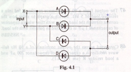
In the
circuit of Fig 4.1, the 4 diodes, A,B,C,D are connected to form a bridge
rectifier. The diodes may be assume to be ideal.
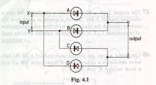
(a)(i)
On the Fig. 4.1, mark with a + sign the positive output terminal
(ii) State which diodes do not conduct when input terminal X is positive
with respect to input terminal Y
(b)The
input terminals X and Y are connected to the secondary coil of an ideal
transformer. The primary coil is connected to a 240Vrms alternating
supply. The input to the bridge rectifier is to be 12Vrms.
(i)
what is the value of the ratio [no. of turns on secondary coil] /
[ no. of turns on primary coil] ?
(ii)
an ideal diode does not conduct when a potential difference is connected
in one direction across the diode. The max. potential difference which
can be applied in this direction across a real diode before it conducts
is known as the breakdown voltage of the diode. Calculate the min. breakdown
voltage of the diode in Fig 4.1 if the circuit is to function correctly. |