|
|
| In this
section, we assume that the AC signal is already rectified. We shall attempt
to try to smooth the signal as the rectified signal is full of 'bumps'
and is thus not a smooth DC signal. |
Explanation

|
|
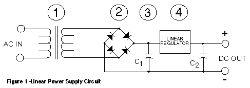
1.
Voltage Transformation
The
first step is to convert the building AC line voltage into another more
suitable voltage. A transformer is used to step down the AC line voltage
to 24 VAC. The transformer also provides some isolation by electrically
separating the AC neutral or ground and the power supply output common.
|
2.
Rectification
The
stepped down 24 VAC voltage is then rectified or converted into a pulsating
DC voltage. A common method of making this conversion is to use a bridge
rectifier. The bridge rectifier consists of four diodes arranged as shown
in Figure 1 and produces a voltage wave form as shown in Figure 2.
|
|
3.
Filtering
The
pulsating full wave rectified DC voltage is smoothed by a filter capacitor.
This capacitor is a large-value electrolytic capacitor which holds its
charge between half cycles of the rectified DC voltage and produces the
voltage shown in Figure 2.
|
|
4.
Regulation
The
filtered DC voltage is controlled by a linear regulator to give a constant
output voltage, even with variations of the input line voltage, the output
load and temperature. The linear regulator is usually an IC regulator but
may also be a discrete circuit when certain performance characteristics
must be enhanced. The regulator also helps to suppress any output ripple
voltage by means of its regulating action. Ripple is the magnitude (usually
measured in millivolts peak-to-peak) of AC voltage on the output of a power
supply as the result of feed through of the rectified line frequency.
|
Thus
a signal as shown in the graph (Fig.2) below is obtained

|
FACTORS
AFFECTING SMOOTHING:
-
CAPACITANCE
-
RATE OF
DISCHARGE
-
FREQUENCY
OF THE A.C. SIGNAL
-
TYPE OF
RECTIFICATION
Back  Continue Continue
|
|
|