| This
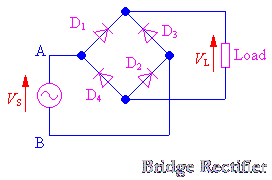
can be done by using 4 p-n junction diodes connected in a bridge format
(a bridge rectifier) as shown in diagram below:
Explanation:
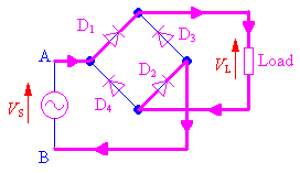
 During
the positive half cycle of the input voltage (see the diagram below for
actual current flow), when A is positive with respect to B, Diodes D1 and
D2 are forward biased, while D3 and D4 are reverse liased. Hence D1 and
D2 will conduct while D3 and D4 are off.The currect takes the path from
A to D1 to D2 then to Load, R then to B, giving rise to an output voltage,
which is approximately equal to the input voltage.

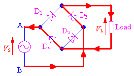
During
the negative half cycle of the input voltage (see the diagram below for
actual current flow), when A is negative with respect to B, diodes D1 and
D2 are now off while D3 and D4 conduct. Hence the current will take the
path of B to D3 to the load then to D4 and to A. Thus the current through
the load is unidirectional and so is its output voltage (top positive with
respect to bottom)

 This
way, both halves of the a.c. voltage are rectified,and we have a full-wave
rectified voltage across R! This
way, both halves of the a.c. voltage are rectified,and we have a full-wave
rectified voltage across R!
Back  Continue Continue
|